
PLFM_RADAR and AERIS-10: Inside an Open-Source 10.5 GHz Phased Array Radar
Radar systems have traditionally been associated with expensive military, aerospace, and industrial equipment. Modern RF electronics, high-speed digital processing, FPGA technology, and open-source hardware are changing that picture. The PLFM_RADAR project, now presented as AERIS-10, is an interesting example of how many of the technologies used in sophisticated radar systems can be combined into an open-source platform.
AERIS-10 is an open-source 10.5 GHz Pulse Linear Frequency Modulated (LFM) phased array radar. The project provides hardware designs, firmware, software, simulations, documentation, and manufacturing files. Its stated purpose is to provide researchers, developers, universities, and advanced electronics enthusiasts with a platform for experimenting with radar signal processing, phased-array beamforming, Doppler processing, and target detection.
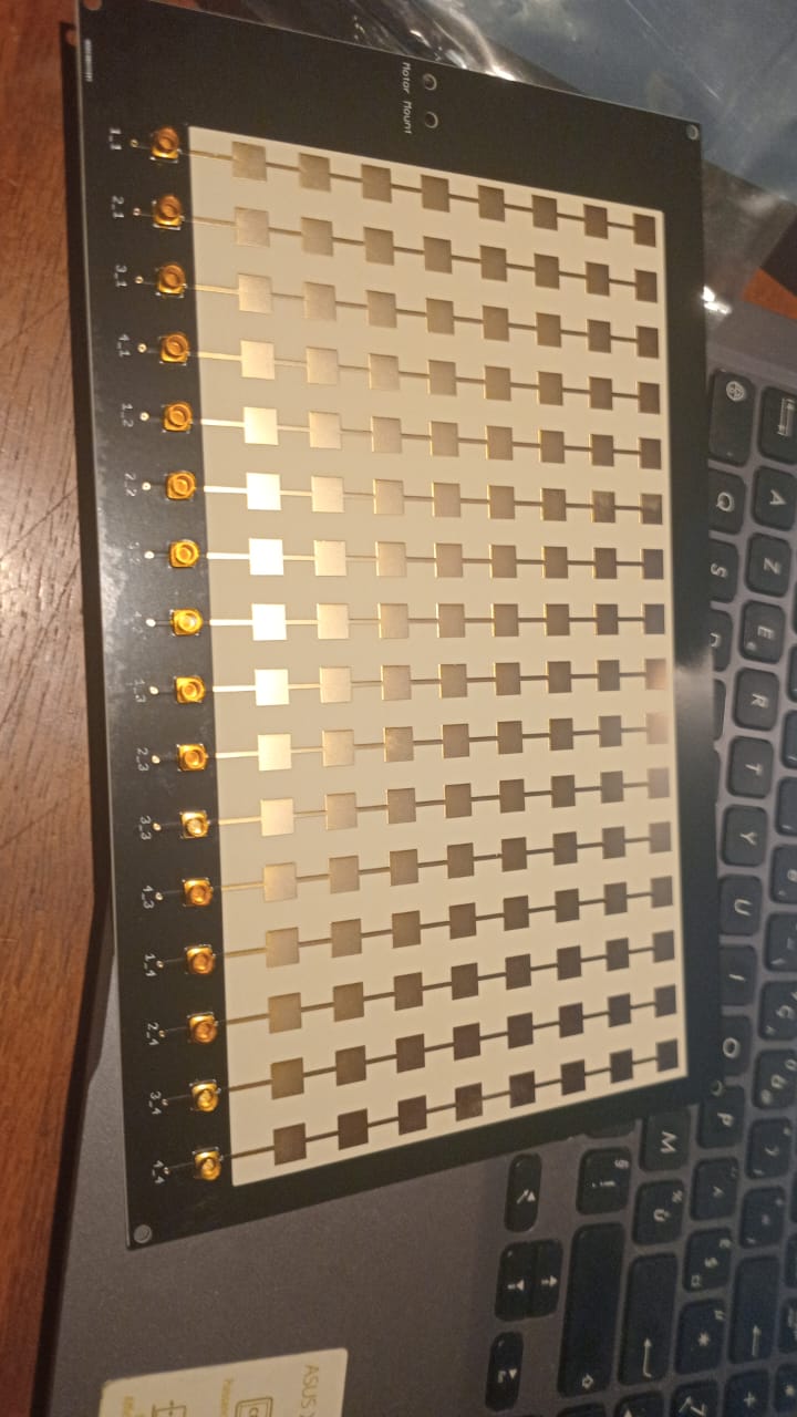
The repository currently describes two principal configurations: the AERIS-10N, designed around an 8×16 patch antenna array with a stated range of approximately 3 km, and the more powerful AERIS-10E, using a 32×16 dielectric-filled slotted-waveguide array and a stated range of approximately 20 km. Both systems operate around 10.5 GHz and combine electronic beam steering with mechanical rotation.
What Is PLFM Radar?
PLFM stands for Pulse Linear Frequency Modulation. In simple terms, the radar transmits short pulses whose frequency changes progressively during each pulse. This changing-frequency signal is commonly called a chirp.
Instead of transmitting a single-frequency pulse, the radar transmits a controlled frequency sweep. When the reflected signal returns from an object, digital signal processing can compare the received waveform with the transmitted waveform.
One of the important advantages of this technique is pulse compression.
A relatively long coded or frequency-modulated pulse can provide useful transmitted energy while digital processing can compress the received pulse in time. This allows the radar to obtain useful range resolution without requiring an extremely short, high-power transmitted pulse.
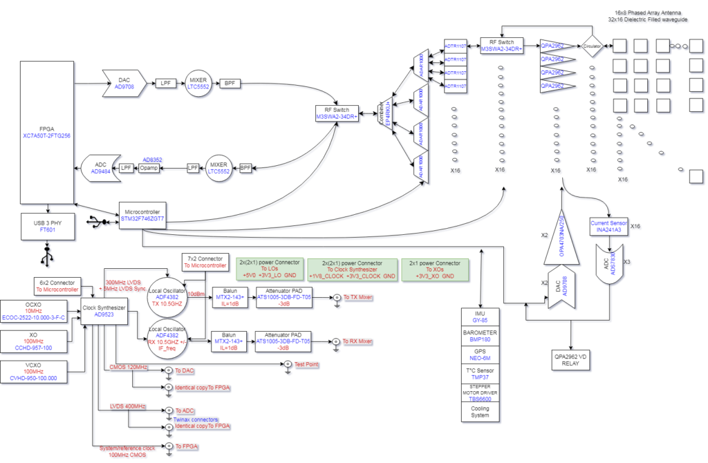
The AERIS-10 architecture uses a DAC to generate the radar chirp, RF circuitry to translate the signal to the operating frequency, antenna elements to transmit and receive the electromagnetic energy, and an FPGA to perform much of the computationally intensive signal processing.
The Overall Hardware Architecture
AERIS-10 is not a single PCB. It is a collection of interconnected electronic and mechanical subsystems.
The major sections include:
- Power management
- Frequency synthesis and clock distribution
- Digital processing
- DAC and ADC interfaces
- RF mixers
- Beamforming circuits
- Transmit/receive front ends
- Power amplifiers
- Antenna arrays
- GPS and inertial sensors
- Motorized mechanical scanning
- Cooling
- Enclosure and mechanical components
This modular architecture is particularly important for a project of this complexity. Separating the power, frequency, RF, digital, and mechanical functions makes the system easier to develop and test.
The repository contains schematics, PCB layouts, BOM/CPL information, simulation material, firmware, mechanical drawings, and supporting documentation.
Frequency Generation and Clocking
One of the most important parts of a radar is its timing and frequency reference.
AERIS-10 uses an AD9523-1 low-jitter clock generator as an important part of its clock architecture. The clock system provides phase-aligned references for the RF synthesizers, DAC, ADC, and FPGA.
This is critical because radar signal processing depends heavily on precise timing and frequency relationships.
The system uses ADF4382 frequency synthesizers for RF frequency generation. The clocking architecture allows the digital and RF sections to operate from controlled references rather than independent oscillators.
In a radar, small timing and phase errors can become significant when signals from multiple antenna elements are combined. Consequently, clock distribution is not simply a matter of providing a clock to each circuit; maintaining appropriate synchronization between the different sections is an important part of the system design.
Digital Chirp Generation
The radar waveform begins in the digital domain.
The system uses a DAC, or Digital-to-Analog Converter, to generate the programmed radar waveform. The FPGA participates in generating the PLFM chirp and coordinating the waveform generation process.
The basic chain can be represented conceptually as:
Digital waveform → DAC → intermediate-frequency/RF processing → transmit beamforming → antenna
The advantage of digital waveform generation is flexibility. Software and FPGA logic can control waveform characteristics without requiring a completely different analog oscillator for every waveform.
This is one of the major differences between modern software-defined radar architectures and older analog radar systems.
RF Conversion
The DAC-generated signal is not necessarily transmitted directly at 10.5 GHz.
AERIS-10 uses LTC5552 microwave mixers for frequency conversion. These devices participate in the up-conversion and down-conversion paths.
During transmission, the digitally generated signal is converted into the appropriate RF frequency range. During reception, the returned RF signal is translated into a frequency range that the ADC and digital processing chain can handle.
This division between RF hardware and digital processing is fundamental to modern radar design.
The RF circuitry handles the very high-frequency electromagnetic signal, while the FPGA handles the mathematical processing required to turn received samples into useful radar information.
Phased Array and Electronic Beam Steering
One of the most interesting aspects of AERIS-10 is its phased-array architecture.
A phased array contains multiple antenna elements. By controlling the relative phase of the signals associated with those elements, the electromagnetic energy can be directed electronically.
AERIS-10 uses ADAR1000 beamforming devices in its RF architecture. The repository describes four four-channel ADAR1000 devices associated with the transmit and receive beamforming chains.
Instead of mechanically pointing the antenna for every small change in direction, the radar can electronically steer its beam within the capabilities of the array.
The project specifies electronic steering of approximately ±45 degrees. Mechanical rotation can then provide wider-area scanning, with the system using a stepper motor for rotational movement.
This combination is particularly interesting:
Electronic steering + mechanical rotation
Electronic steering provides rapid directional control, while mechanical rotation can extend the overall field of coverage.
Transmit and Receive Front End
The antenna array is only one part of the RF system.
AERIS-10 uses ADTR1107 front-end devices in its transmit and receive chains. The repository describes these devices as being used for low-noise amplification on reception and power amplification on transmission.
The receive side needs to deal with very weak signals. A reflected radar signal can be dramatically weaker than the original transmitted signal, so the receiver must amplify it while attempting to preserve signal quality.
The transmit side has the opposite requirement: it must deliver sufficient RF energy into the antenna system.
The system therefore has to manage gain, noise, linearity, isolation, switching, and thermal conditions across the RF chain.
Power Amplifier Architecture
The two AERIS-10 configurations differ substantially in their RF power architecture.
The AERIS-10N configuration is described with approximately 1 W per channel across 16 channels, while the extended configuration uses dedicated power amplifier boards with 10 W GaN amplifiers for each of its 16 channels.
The extended version therefore requires substantially more attention to power distribution and thermal management.
The repository specifically describes QPA2962 GaN amplifiers on the AERIS-10E power amplifier boards. GaN technology is attractive for RF applications because of its combination of power capability, frequency performance, and efficiency.
The power amplifier section also demonstrates why a radar is not simply an RF board with an antenna attached. Power conversion, current measurement, cooling, control loops, and protection become important engineering problems.
Thermal Monitoring and Power Control
AERIS-10 includes a significant amount of monitoring and control hardware.
The STM32 microcontroller manages power sequencing and monitors several system parameters.
The project uses current sensing for the power amplifier channels. The repository describes 5 mΩ shunts together with INA241A3 current-sense amplifiers, allowing the system to measure the operating current of the individual amplifier channels.
It also uses DAC channels to control amplifier gate voltages.
This creates a closed-loop approach in which the system can monitor and control the RF power stages rather than simply switching them on and leaving them uncontrolled.
Thermal monitoring is also integrated into the system. Thermistors are used to monitor temperature, with the STM32 controlling cooling fans when thermal conditions exceed configured thresholds.
The FPGA: The Computational Core
The FPGA is arguably the most important digital component in the system.
The current repository describes an AMD/Xilinx Artix-7 XC7A50T FPGA implementation for the main processing chain.
Why use an FPGA instead of doing everything on a conventional CPU?
Radar signal processing involves large quantities of sampled data and many operations that must happen with predictable timing. FPGA logic can perform many operations concurrently.
The AERIS-10 FPGA performs several important tasks:
- Raw ADC data acquisition
- I/Q baseband down-conversion
- Decimation
- Digital filtering
- Forward FFT processing
- Pulse compression
- Doppler processing
- MTI processing
- CFAR detection
- Communication with the rest of the system
The repository’s recent releases also show continuing FPGA development, including a 2048-point FFT implementation and timing-closure work.
I/Q Baseband Processing
The received signal contains information in both amplitude and phase.
Radar systems commonly represent this information using I/Q, meaning in-phase and quadrature components.
The FPGA performs digital down-conversion to transform the sampled RF/IF information into a more convenient baseband representation.
After down-conversion, the data can be filtered and decimated.
Decimation reduces the sampling rate after appropriate filtering. This can significantly reduce the amount of data that later processing stages need to handle.
The result is a digital signal that is much easier to process for range and Doppler information.
Pulse Compression
Pulse compression is one of the central signal-processing techniques in a PLFM radar.
The transmitted chirp contains a known frequency progression. When the reflected signal arrives, the FPGA can correlate the received signal with the expected waveform.
The result is a compressed peak.
The position of that peak corresponds to the signal’s delay, which can then be associated with target range.
This is one of the areas where digital signal processing provides a major advantage. The radar can transmit a waveform designed for useful energy and then use computation to obtain a sharper response.
Doppler Processing
Detecting an object is only part of radar processing.
The radar can also examine how the received signal changes over repeated observations.
Movement produces Doppler frequency shifts.
AERIS-10 uses FFT-based processing to extract Doppler information. By processing a sequence of radar returns, the system can distinguish stationary or slowly changing signals from moving targets.
The Doppler-processing stage is particularly useful when combined with clutter suppression and detection algorithms.
MTI and CFAR
The FPGA also implements MTI and CFAR processing.
MTI stands for Moving Target Indication. Its purpose is to help separate moving objects from relatively stationary background or clutter.
CFAR stands for Constant False Alarm Rate.
A radar receiver does not simply ask, “Is this signal strong?”
Environmental noise and clutter vary. A fixed threshold can therefore produce too many false detections in one situation and miss weak targets in another.
CFAR algorithms adapt the detection threshold according to the surrounding signal environment.
This allows the system to make more intelligent detection decisions from the processed radar data.
STM32 Microcontroller
The FPGA handles the high-throughput signal-processing workload, while an STM32F746xx microcontroller handles system management.
This division is sensible.
The FPGA is excellent at deterministic parallel processing, while the STM32 is well suited to configuration, peripheral management, sequencing, sensors, motors, and communications.
The repository identifies several STM32 responsibilities, including:
- Power sequencing
- FPGA communication
- RF synthesizer configuration
- Beamformer configuration
- Current monitoring
- Amplifier control
- GPS integration
- IMU integration
- Barometric sensing
- Stepper-motor control
- Thermal monitoring
- RF switch control
This makes the STM32 effectively the system-management controller surrounding the FPGA signal-processing engine.
GPS, IMU and Mechanical Scanning
Radar measurements become more useful when the system knows its own position and orientation.
AERIS-10 integrates a UM982 GPS module and a GY-85 IMU.
GPS information can be used for map positioning and detection tagging, while inertial measurements can help compensate for the radar’s physical orientation.
The system also incorporates a barometer and stepper motor.
The stepper motor provides mechanical rotation, allowing the antenna assembly to scan around a wider angular area.
A slip-ring is included among the mechanical components so electrical connections can be maintained while the assembly rotates.
Python Software and User Interface
The hardware would be considerably harder to use without software.
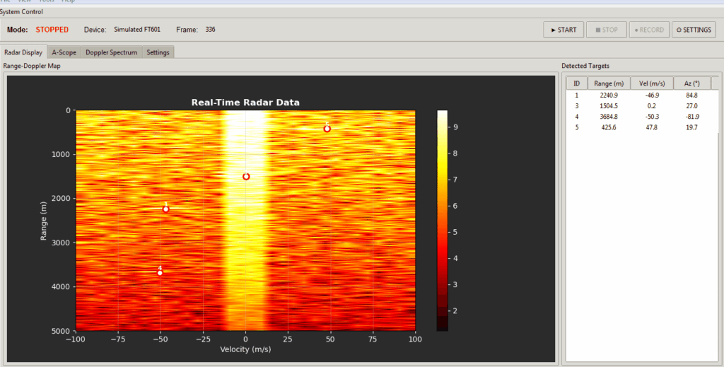
AERIS-10 includes a Python-based GUI designed to provide a user interface for the radar system.
The GUI provides functions such as real-time target visualization, map integration, radar control, and system interaction.
This creates a software hierarchy:
Python GUI → STM32 control layer → FPGA processing → RF hardware
The FPGA produces processed radar information. The STM32 handles system-level control and communication. The Python application provides the human-facing interface.
This separation is useful because each layer can evolve independently.
A developer can improve visualization without redesigning the FPGA. An FPGA developer can optimize signal processing without rewriting the entire GUI.
Software Architecture
The repository separates its firmware into different areas. The project contains an STM32 microcontroller firmware section and an FPGA firmware section.
The FPGA area contains RTL, constraints, testbenches, and build-related material. The microcontroller section contains STM32 firmware and associated tests.
This is important from a software-engineering perspective.
A radar is not simply an embedded program. It is effectively a distributed real-time computing system consisting of:
- FPGA hardware logic
- Microcontroller firmware
- RF device configuration
- Host computer software
- Signal-processing algorithms
- Hardware control
- Sensor processing
The open-source repository provides developers with access to these different layers rather than treating the radar as a black box.
From Reflected Signal to Target on a Screen
The complete process can be simplified into a sequence.
First, the FPGA generates the digital LFM waveform.
The DAC converts the digital waveform into an analog signal.
The RF chain translates the signal to the radar’s operating frequency.
The beamforming hardware distributes the signal through the appropriate antenna channels.
The antenna array transmits the electromagnetic energy.
A portion of the energy may be reflected from an object.
The receive array captures the returned energy.
The RF front end amplifies and converts the received signal.
The ADC digitizes it.
The FPGA performs digital down-conversion, filtering and decimation.
Pulse compression produces range information.
FFT-based processing extracts Doppler information.
MTI and CFAR algorithms help identify meaningful detections.
The STM32 combines the radar information with system and sensor information.
Finally, the Python software displays the processed information to the operator.
This entire chain has to operate reliably and with carefully controlled timing.
Why AERIS-10 Is Interesting
The most interesting aspect of AERIS-10 is not any individual component.
The project demonstrates how many different engineering disciplines can be combined into one open-source platform.
It involves:
RF engineering for the 10.5 GHz signal chain.
Antenna engineering for the phased-array structures.
Digital electronics for the ADC, DAC, clocking and interfaces.
FPGA engineering for real-time signal processing.
Embedded software for the STM32.
Python software development for the GUI.
Mechanical engineering for the rotating antenna assembly and enclosure.
Power electronics for the various regulated supply rails.
Thermal engineering for RF amplifier cooling.
Signal processing for pulse compression, FFT, Doppler, MTI and CFAR.
The repository also provides simulations, manufacturing files, component documentation, mechanical drawings, and technical documentation, making it considerably more than a conceptual radar diagram.
Open-Source Hardware and Software
Another significant feature is the project’s licensing approach.
The repository states that its hardware documentation is licensed under the CERN Open Hardware Licence Version 2 – Permissive (CERN-OHL-P), while software and firmware components are generally under the MIT License.
That distinction is useful because hardware and software have different licensing requirements.
The availability of schematics, PCB layouts, BOM files, manufacturing outputs, firmware, and software makes the project particularly interesting for education, research, prototyping, and engineering experimentation.
Conclusion
PLFM_RADAR, now known as AERIS-10, provides an unusually complete look into the architecture of a modern phased-array radar.
At the hardware level, it combines a 10.5 GHz RF system, precision clock generation, DAC and ADC conversion, microwave mixers, phased-array beamforming, transmit/receive front ends, power amplifiers, antennas, sensors, cooling, and mechanical scanning.
At the software level, it combines FPGA-based real-time signal processing with STM32 system control and a Python graphical interface.
The real engineering achievement is the integration of these systems.
A radar only becomes useful when waveform generation, RF electronics, antennas, timing, digital processing, embedded control, and visualization all work together. AERIS-10 provides an open-source environment in which engineers and researchers can study exactly that interaction.
For anyone interested in RF electronics, FPGA development, digital signal processing, embedded systems, antennas, or advanced engineering projects, the PLFM_RADAR repository is therefore much more than a collection of circuit diagrams. It is an example of how a complete modern radar architecture can be approached as an open engineering project.
The project continues to evolve, with recent releases addressing FPGA processing, timing closure, reset distribution, automatic gain control, and production-oriented hardware bring-up.
The AERIS-10 repository is available on GitHub: PLFM_RADAR / AERIS-10

